
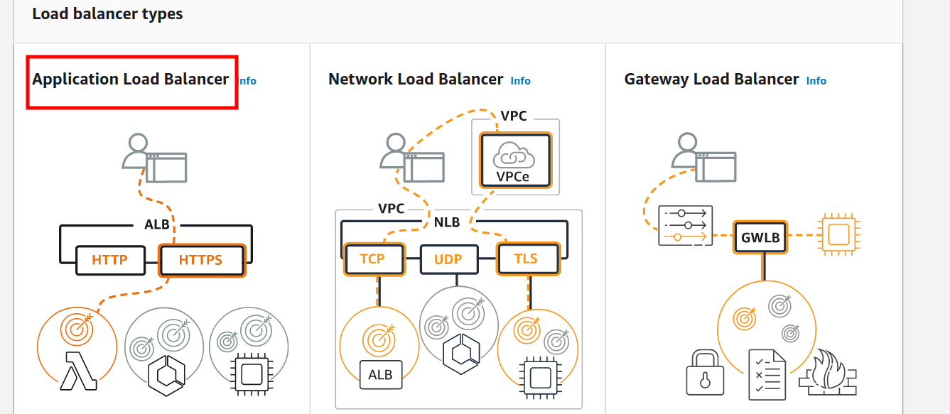
In AWS, ELB or Elastic Load Balancing is a concept where the servers can be added or released as per the demand of our application. The incoming traffic from an application is distributed among multiple targets. These targets can be EC2 instances, containers, and IP addresses in one or several Availability Zones. Supported types of AWS Elastic Load Balancers are Application Load Balancers(ALB), Network Load Balancers(NLB), Gateway Load Balancers(recently launched), and Classic Load Balancers. These load balancers have different configurations, for e.g.,
- Application Load Balancer: It works by automatically distributing the incoming application traffic between two or more EC2 instances. We can define routing rules as per the content of the request(content-based routing). It is a layer 7 load balancer.
- Network Load Balancers: NLB uses IP protocol data (TCP and UDP) to route connections to AWS resources like EC2, microservices and containers. It is a layer 4 load balancer.
- Gateway Load Balancer: These are used with third-party virtual appliances like NextGen firewalls(NGFW), IPS, IDS etc. running on EC2 instances. It works by placing a single gateway for traffic from multiple virtual appliances and these multiple virtual appliances can be scaled up or scaled down as per the demand. This is good for the stability of the network. It is a layer 3(Gateway) plus layer 4(Load Balancing) load balancer.
- Classic Load Balancer: CLB is a legacy load balancer of AWS which is used for load balancing across multiple EC2 instances. It is recommended for applications designed within the EC2-Classic network. It is a layer 4/7 load balancer. It is recommended by AWS to avoid this load balancer.
Overview of this Guide
In this tutorial, we will configure path-based routing for Application Load Balancer on AWS. We are going to use an IAM user account with limited privileges required for this task. We have the following resources for this experiment:
- Two Availability Zones with each containing at least one EC2 instance.
- A VPC has a minimum of one public subnet in each of the above two Availability Zones. This public subnet will be used for configuring the load balancer.
- Install a web server on each instance and allow port 80 access on these instances using the security group.
Configuration of EC2 instances
For this guide, we have configured two Amazon Linux EC2 instances with apache Httpd installed on both of them. On one server we have a ‘signin’ directory and an index.html file inside it with the contents: “Welcome User? Sign in to proceed…”
On another server we have a ‘signup’ directory and an index.html file inside it with the contents: “New User? Sign Up First…”
Both the ‘signin’ and ‘signup’ directories are inside the root directory(/var/www/html).
Configuring the Target group
Step 1. For routing the request we will first create two target groups, one for each server. Open the EC2 console and on left side panel, find and select ‘Target Groups’ (It is under Load balancing):
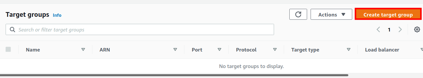
Step 2. On the new page, click on the ‘Create target group’ button:
<img alt="Creating target group" data-ezsrc="https://kirelos.com/wp-content/uploads/2022/04/echo/image17.png62614554c68b6.jpg" ezimgfmt="rs rscb5 src ng ngcb5" height="138" loading="lazy" src="data:image/svg xml,” width=”750″>
Step 3. We are now on the ‘Specify group details’ page. Under basic configuration, do the following:
- Choose a target type: Select ‘Instances’ here.
- Target group name: Give a suitable name to the target group(‘Sign-In’ in our case.)
- Protocol: HTTP
- Port: 80
- VPC: Select your VPC Name here.
- Protocol version: Keep the default selected one.(HTTP1)
Under the ‘Health checks’ settings:
Health check protocol: HTTP
Health check path: ‘Path you want to use’(‘/signin’ in our case)
Keep the ‘Advanced health check settings’ to default. Add tags if you need them(Optional). Click ‘Next’ to continue.
Registering EC2 Instances to the Target Groups
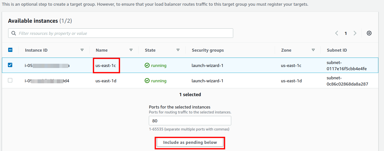
Step 3. Now add one of the EC2 instances to the above target groups. Select an instance and then click on ‘Include as pending below’ button
<img alt="Registering EC2 Instances to the Target Groups" data-ezsrc="https://kirelos.com/wp-content/uploads/2022/04/echo/image10.png62614554ea0ad.jpg" ezimgfmt="rs rscb5 src ng ngcb5" height="295" loading="lazy" src="data:image/svg xml,” width=”750″>
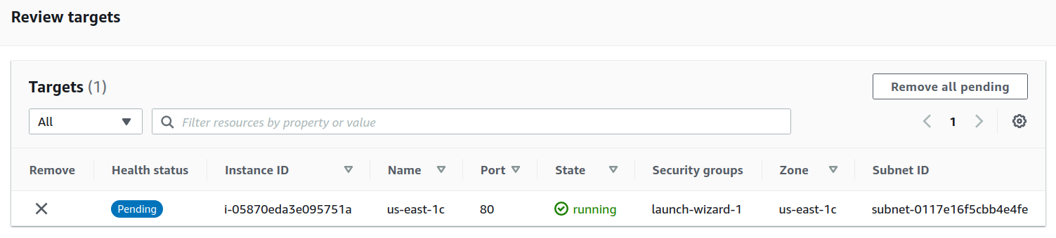
The above-selected instance will appear under ‘Review targets’. Now click on ‘Create target group’.
<img alt="Review the targets" data-ezsrc="https://kirelos.com/wp-content/uploads/2022/04/echo/image18.png62614555177f4.jpg" ezimgfmt="rs rscb5 src ng ngcb5" height="169" loading="lazy" src="data:image/svg xml,” width=”750″>
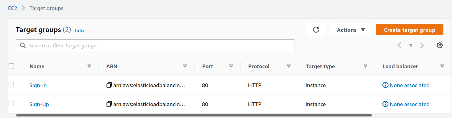
On the next window again click ‘continue’. Now repeat the same procedure for another Target group and name it as ‘Sign-Up’. Use another instance( in another Availability zone) with this Target group and use a different Health check path(‘/signup’ in our case):
Creating the Application Load Balancer
Step 1. From the EC2 console, head to Load Balancers and click on Create Load Balancer button and then select ‘Application Load Balancer’ shown on the new page:
<img alt="Creating the Application Load Balancer" data-ezsrc="https://kirelos.com/wp-content/uploads/2022/04/echo/image19.png62614555664a1.jpg" ezimgfmt="rs rscb5 src ng ngcb5" height="327" loading="lazy" src="data:image/svg xml,” width=”750″>
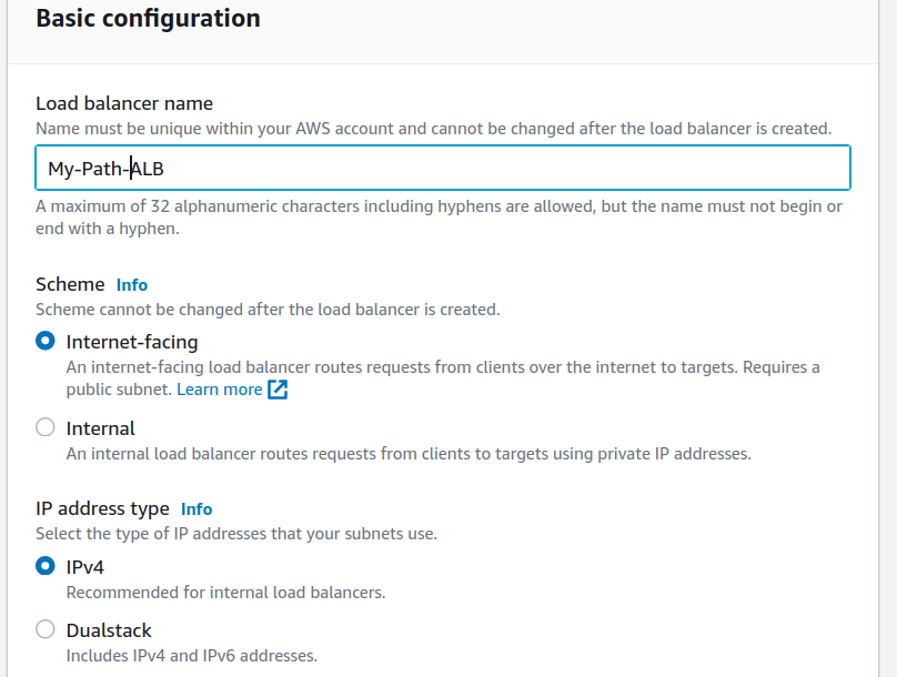
Step 2. Give a suitable name(here ‘My-Path-ALB’) to your load balancer. Keep the Scheme to default (‘Internet-facing’), Select IP address type as IPv4
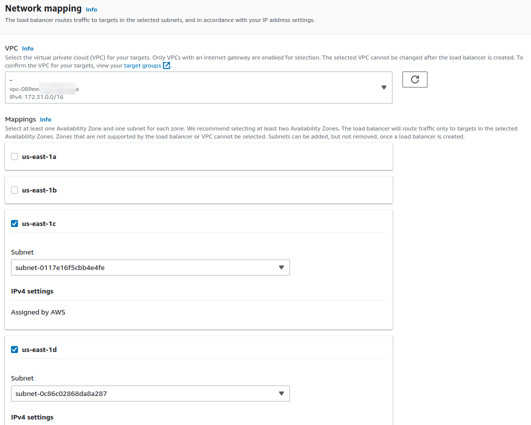
Step 3. Under the Network mapping section, select the target VPC and in Mappings section, select the two Availability zones containing your targets to which load balancer will route the traffic.
<img alt="Configuring the load balancer – 2" data-ezsrc="https://kirelos.com/wp-content/uploads/2022/04/echo/image11.png62614555af007.jpg" ezimgfmt="rs rscb5 src ng ngcb5" height="600" loading="lazy" src="data:image/svg xml,” width=”750″>
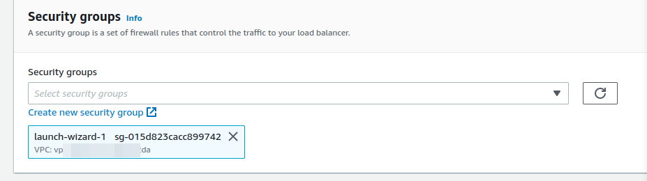
Step 4. Configure Security Groups for the load balancer and allow your target port (port 80 in our case) to listen on:
<img alt="Configuring the load balancer – 3" data-ezsrc="https://kirelos.com/wp-content/uploads/2022/04/echo/image13.png62614555cfa1c.jpg" ezimgfmt="rs rscb5 src ng ngcb5" height="210" loading="lazy" src="data:image/svg xml,” width=”750″>
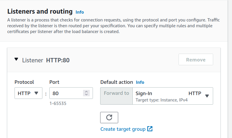
Step 5. Select a listener(HTTP in our case) and enter a port to listen on or choose to stick with the default port 80 for HTTP requests. Under the Default action, select ‘Sign-in’ target for ‘forward to’ column:
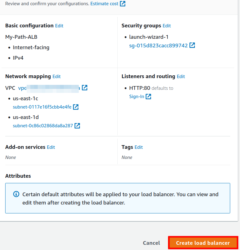
Step 6. Optional steps can be skipped. Now review the summary and hit the ‘Create load balancer’ button:
Adding Host-based Forwarding Rules
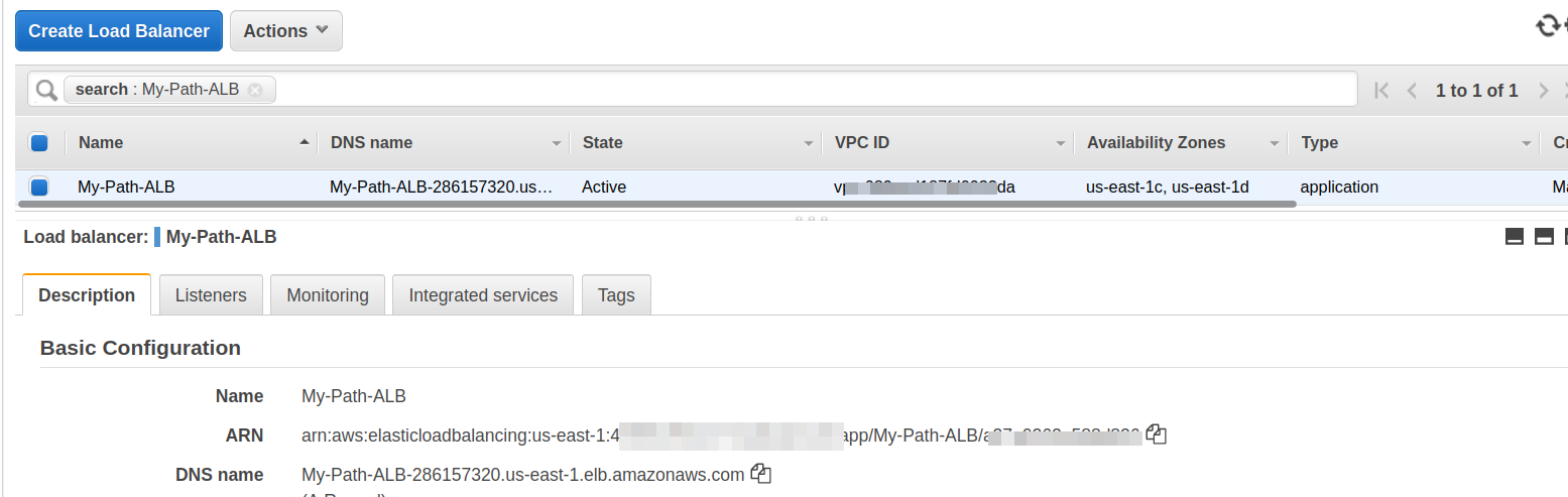
Step 1. Now again go to the ‘Load Balancers’ page and find your target load balancer here:
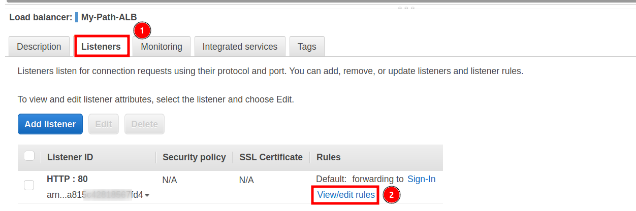
Step 2. Once the ALB status changes to Active, we will proceed with Forwarding Rules. Click on the Load Balancer name and then go to the Listeners tab
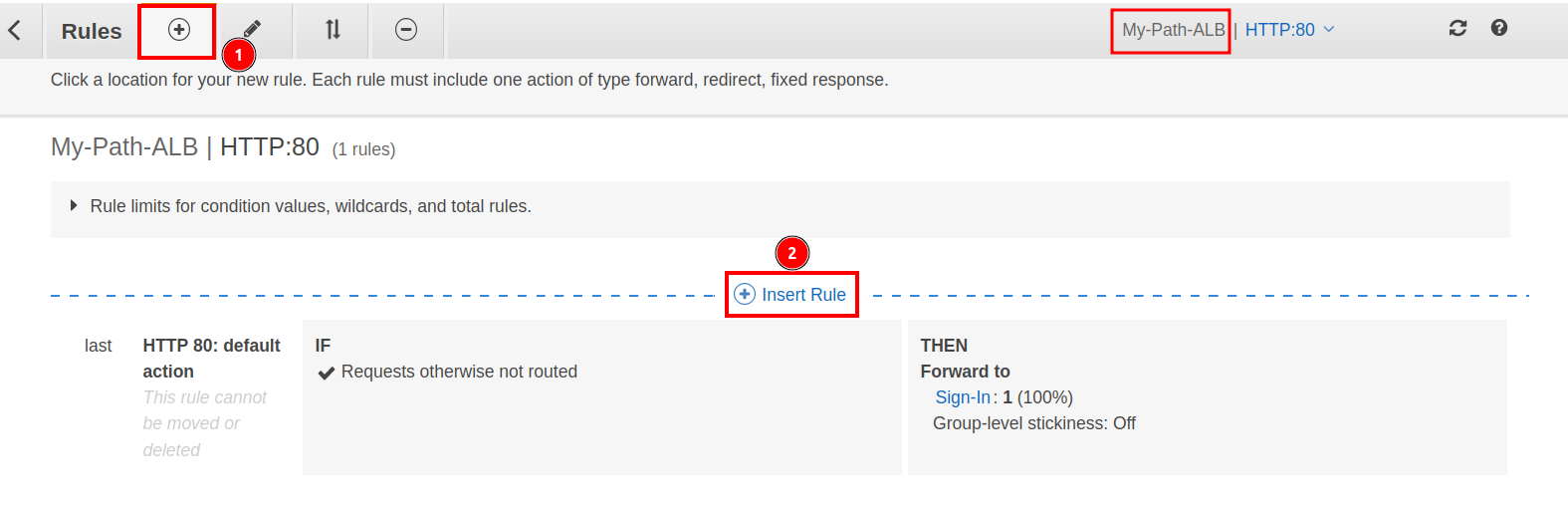
Step 3. Click on ‘View/Edit rules’ under ‘Rules’ column and then click on the ‘ ’ symbol followed by ‘Insert Rule’:
Step 4. Under the ‘IF(all match) column, click on the ‘ Add condition’ drop-down arrow and select ‘Host’ as the Rule type and put your hostname or domain name (‘www.signin.tecofers.com’ in our case) in the text field corresponding to ‘is’ label.
Step 5. From the ‘Then’ column, click on ‘ Add action’ drop-down arrow and select ‘Forward to’ as the action. Here select the target group ‘Sign-In’.
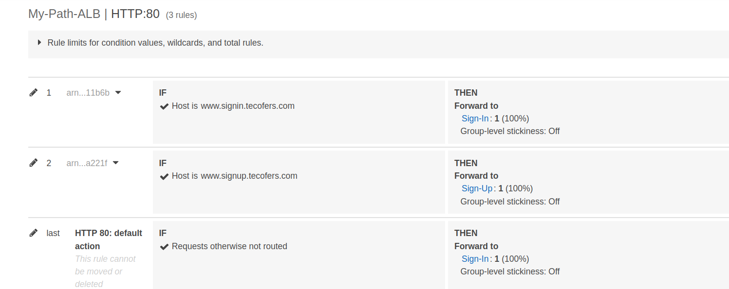
Repeat the above steps 2 and 3 for the target group ‘SignUp’ with hostname or domain name (‘www.signup.tecofers.com’ in our case). After saving the rules, we will have two rules:
Advertisement
The last rule is for default action if the above two conditions are not satisfied.
Registering the domain in Route 53
To register the host/domains for the host-based routing over the internet, we need to add the DNS name of their corresponding EC2 instances with their hostname/domain name inside Route 53.
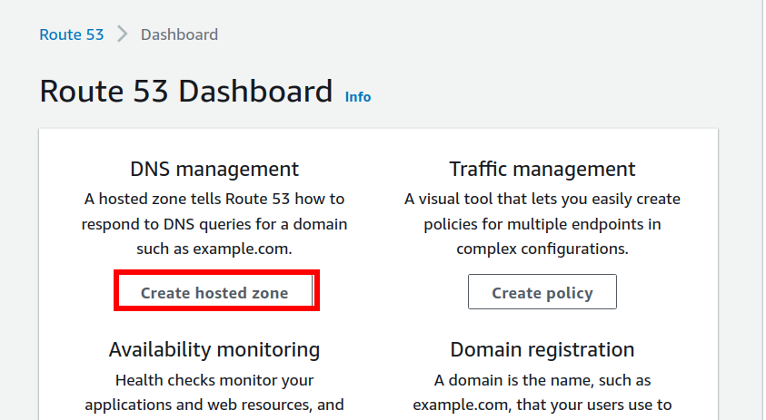
Step 1. Open Route 53 dashboard from the management console and click on ‘Create hosted zone’:
<img alt="Route 53 dashboard" data-ezsrc="https://kirelos.com/wp-content/uploads/2022/04/echo/image12.png6261455705479.jpg" ezimgfmt="rs rscb5 src ng ngcb5" height="411" loading="lazy" src="data:image/svg xml,” width=”750″>
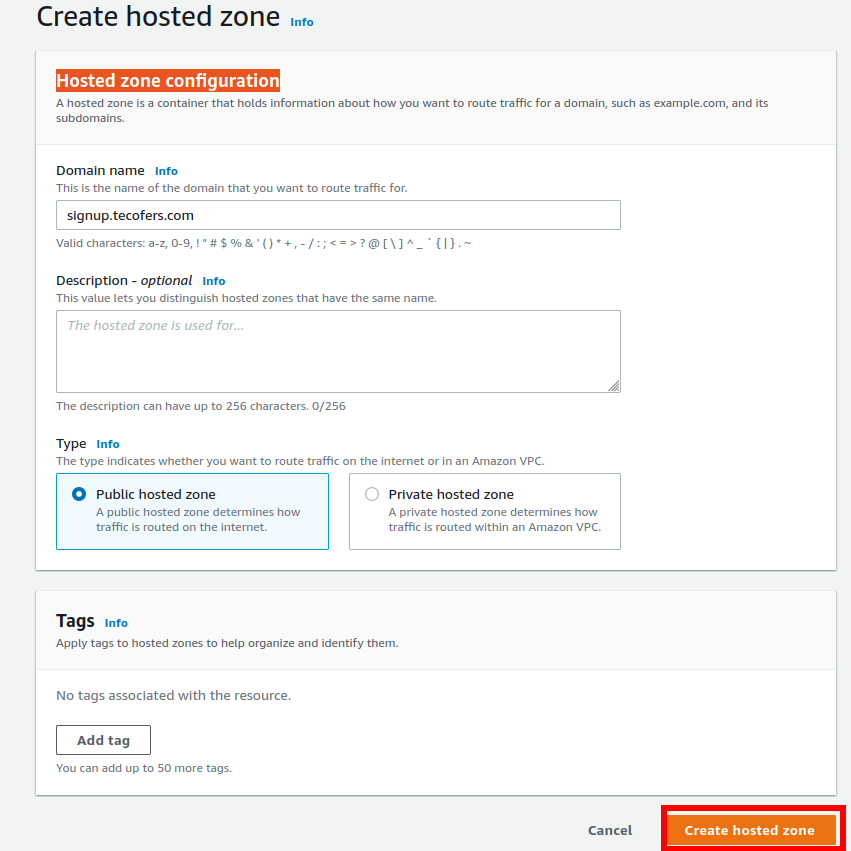
Step 2. On the Hosted zone configuration page, enter the domain name and select type as ‘Public hosted zone’ and select ‘Create hosted zone’:
<img alt="Creating Hosted zone 1" data-ezsrc="https://kirelos.com/wp-content/uploads/2022/04/echo/image20.png6261455741999.jpg" ezimgfmt="rs rscb5 src ng ngcb5" height="750" loading="lazy" src="data:image/svg xml,” width=”750″>
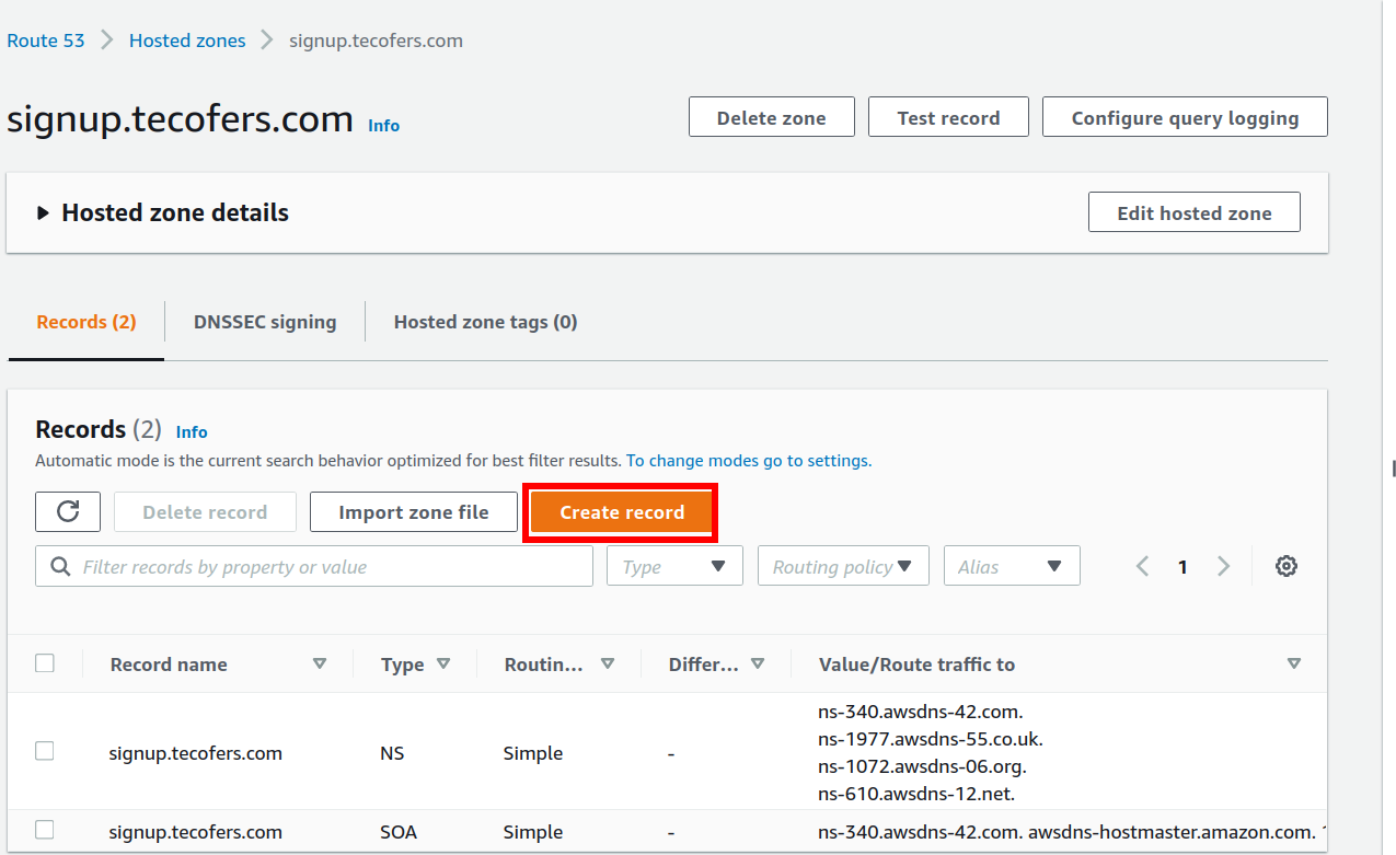
Step 3. On the new page click on ‘Create Record’:
<img alt="Creating record for the hosted zone" data-ezsrc="https://kirelos.com/wp-content/uploads/2022/04/echo/image21.png626145576c5a7.jpg" ezimgfmt="rs rscb5 src ng ngcb5" height="459" loading="lazy" src="data:image/svg xml,” width=”750″>
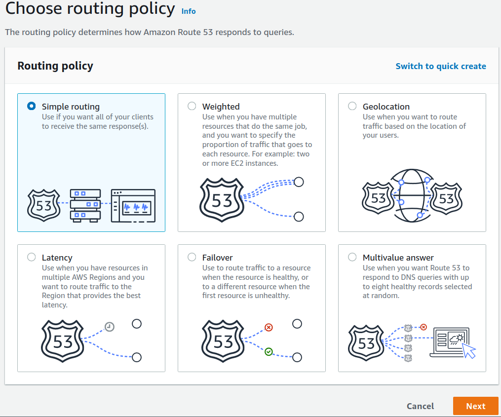
Step 4. On the new page, click on the label ‘Switch to wizard’ and select ‘Simple Routing’ option
<img alt="Select Routing policy" data-ezsrc="https://kirelos.com/wp-content/uploads/2022/04/echo/image15.png626145579d5fb.jpg" ezimgfmt="rs rscb5 src ng ngcb5" height="624" loading="lazy" src="data:image/svg xml,” width=”750″>
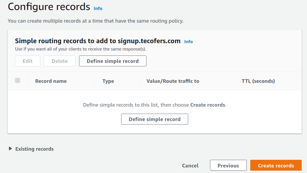
Step 5. Here click on ‘Define simple record’
<img alt="Define simple record" data-ezsrc="https://kirelos.com/wp-content/uploads/2022/04/echo/image7.png62614557c773c.jpg" ezimgfmt="rs rscb5 src ng ngcb5" height="423" loading="lazy" src="data:image/svg xml,” width=”750″>
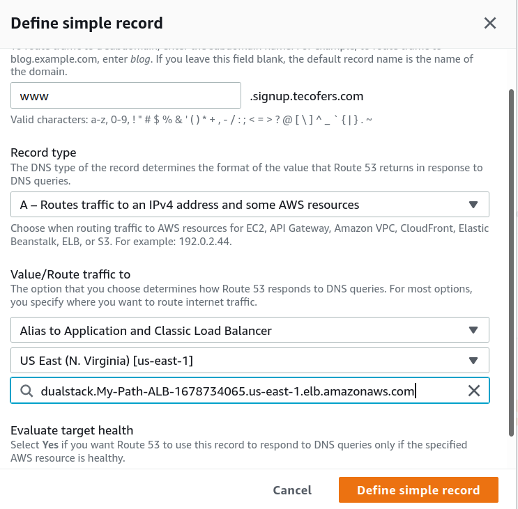
Step 6. Enter various details for this record:
Domain: subdomain corresponding to your hosted zone.
Record type: Select A type here.
Value/Route traffic to:
- Select ‘Alias to Application and Classic Load Balancer’
- Select region where load balancer is
- Select the target load balancer.
Finally hit ‘Define simple record’.
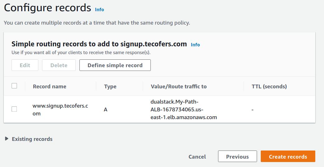
The above record will now appear as shown here:
<img alt="First record" data-ezsrc="https://kirelos.com/wp-content/uploads/2022/04/echo/image16.png626145581e660.jpg" ezimgfmt="rs rscb5 src ng ngcb5" height="387" loading="lazy" src="data:image/svg xml,” width=”750″>
Repeat the above steps for the other host.
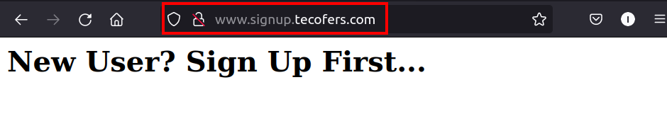
Verifying the setup…
To check if everything is working as expected, open a web browser and paste the DNS of the load balancer and append it with:
1) Hostname for ‘Sign-up’ target
2) Hostname for ‘Sign-In’ target
Conclusion
Congratulations, we have finally configured a working scenario for host-based routing on AWS application load balancer.


